Introduction to Electronic Circuits
Electronics covers a range of topics from DC circuits to microwave engineering. Here we introduce basic the DC circuit theory of passive systems.
DC circuit theory is concerned with systems in which the voltage and current levels
are not changing; that is, there are no pulses or transients. Passive circuits are
those with no amplifying devices such as transistors and vacuum tubes. The only elements
in a passive circuit are power supplies and resistors. In real-
Students studying electronics first look at passive circuits, then AC circuits involving sine waves (e.g., power electronics and wireless circuits). AC circuits add two fundamental components: the inductor and the capacitor. Finally, students study more complex systems (e.g., transmission lines) that involve transients. A transient is a step change in voltage and models the pulses found in digital circuits.
Basic Electronics
You can’t get much simpler than the basic passive circuit. To analyze such a circuit requires only a knowledge of Ohm’s law and Kirchoff’s laws. Ohm’s law states that V = I.R or I = V/R where R is electrical resistance, I is current, and V is voltage. Note that some texts use V for voltage and some E.
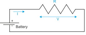
Figure 1 illustrates the simplest possible circuit. The voltage is at the same level everywhere along a conductor. In this example, the battery voltage is V which is applied to the ends of resistor R. The current flowing is, therefore, I = V/R.
If the battery voltage is 3V and the resistor is 160W, the current through R is 3/160 = 0.01875 A = 187.5 mA. Although current is measured in amperes, typical electronic circuits tend to draw milliamps (mA) or microamps (A).
.
Figure 1 Circuit with a single resistor
Resistors in Series and Parallel
In practical circuits, resistors can be in series or in parallel as figure 2 demonstrates. In figure 2(a) two resistors R1 and R2 are wired in series. If two components are in series, the same current must flow through them. The voltage across the resistors may not be the same, but the sum of the voltages across the resistances must add up to the battery voltage; that is, V = V1 + V2.
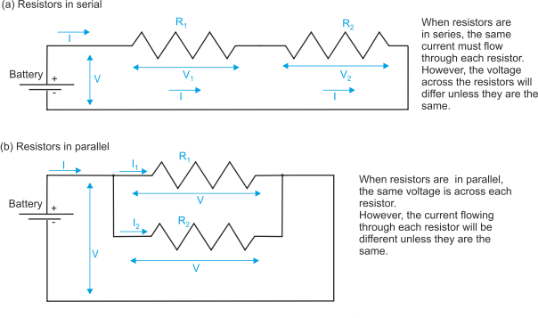
Figure 2 Circuit with resistors in serial or parallel
From figure 2(a) we can say that I = V1/R1 and I = V2/R2.
If the total effective resistance is RT (i.e., the resistance we could substitute for R1 and R2 in series), we can write I = V/RT.
Using simple algebra, V = V1 + V2 = I.R1 + I.R2 = I.RT
Dividing by I, we get RT = R1 + R2. In any serial circuit, the total resistance is equal to the sum of all resistances in series.
Suppose that the battery is 5V, R1 = 100W and R2 = 300W.
The total resistance is given by the sum of resistance; that is 100 + 300 = 400W.
The current flowing through the circuit is 5V/400W = 0.0125A = 12.5mA.
The voltage across the 100W resistor is V = I.R = 0.0125 x 100W = 1.25V and the voltage across the 300W resistor is 0.0125 x 300W = 3.75V. The sum of these two voltages is 1.25 + 3.75 = 5.00V.
Consider now case 2(b) where the resistors are connected in parallel. The voltage across each resistor is the same, but each resistor takes a different share of the total current. We can write:
I = I1 + I2
RT = V/I
I1 = V/R1
I2 = V/R2
Rearranging these equations we get I = I1 + I2 = V/R1 + V/R2 = V/RT
Dividing by V we get: 1/RT = 1/R1 + 1/R2
In this case, the reciprocal of the total resistance is the sum of the reciprocals of the individual resistances. We can rearrange the equation to get RT = 1/(1/R1 + 1/R2)) or RT = R1.R2(R1 + R2).
If we repeat the previous example with the battery = 5V, R1 = 100W and R2 = 300W we get:
Total effective resistance = 1/(1/100 + 1/300) = 1/(0.010 + 0.00333) = 1/0.01333 = 75W.
The current through R1 is given by 5/100 = 50 mA, and the current through R2 is given by 5/300 = 16.667 mA. The total current is 50 mA + 16.667 mA = 66.667 mA.
If we use the equivalent resistance, 75W, we get total current = 5/75 = 66.667 mA.
We can create circuits of arbitrary complexity. But we won’t. Figure 3 represents just a modest step in complexity. Here we have both serial and parallel networks. We can solve the problem exactly as before by noting that the voltage across parallel resistors is the same across each device, and the current flowing through serial resistors is the same through each device. However, we will provide a worked example with given resistor values to avoid tedious algebra.
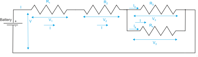
Figure 3 Circuit with resistors in series and parallel
For figure 3 assume that R1 = 50W, R2 = 80W, R3 = 100W, R4 = 200W, R5 = 300W.
We can immediately treat R1 and R2 as a single entity of 50W + 80W = 130W.
Similarly, we can also treat R3 and R4 as a single entity of 100 x 300/ (100 + 300) = 30,000/400 = 75W.
We are now left with two equivalent resistances of 130W and 75W in series to give a total resistance of 130 + 75 = 205W.
From this, we can calculate the current flowing through the battery, I, as 5V/205W = 29.39mA, and so on.
AC Circuits
If passive circuits involving only resistors are energized by alternating currents, the same calculations we used above apply. However, there are two components that have no effects in DC circuits but which determine the operation of AC circuits. These are the capacitor and the inductor. A capacitor has the ability to store an electric charge and an inductor impedes a changing voltage. We provide a brief introduction to the resistor/capacitor (RC) circuit here.